Not known Factual Statements About Wedge Barriers

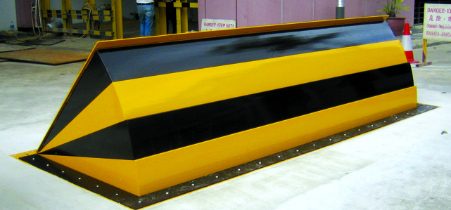
In the adhering to conversation, referral is made to a surface area of a structure to which the wedge-style barrier is mounted. In the detailed personifications, the top side of the anchor is substantially flush with the surface area of the structure. In such embodiments, the wedge-style obstacle may be placed straight to the surface of the structure. However, in other embodiments, the upper side of the support might be a little increased over the surface area of the foundation or a little recessed below the surface area of the structure. 1 is a front perspective sight of an embodiment of a surface-mounted wedge-style obstacle 10. As revealed, the barrier 10 is mounted to a surface 12 of a structure 14(e. g., a superficial foundation ). For instance, the structure
14 and the surface 12 to which the barrier 10 is protected might be made from concrete - Wedge Barriers. 2, the barrier 10 is mounted to or consists of a support or subframe (e. g., support 30 received FIG. 2 )secured beneath the surface 12. The bather 10 might be bolted to the anchor or safeguarded to the anchor by other mechanical bolts. In the detailed embodiment, the obstacle 10 consists of a wedge plate 16, which consists of a part that is considerably parallel with the surface 12 when the obstacle 10 is in the withdrawed placement. In other words, vehicles or people may overlook the obstacle 10 when the barrier 10 is in the withdrawed setting and experience small elevation family member to the surface 12 while on the barrier 10. As talked about in information listed below, when the obstacle 10 remains in the deployed placement, the wedge plate 16 is held and supported in a raised setting by a training system of the barrier 10. Furthermore, the components 18 may be bolted or otherwise mechanically coupled to one an additional. In this manner, fixing or replacement of one or more parts 18 may be simplified and streamlined. That is, repair or replacement of solitary elements
18 might be done quicker, quickly, and cost properly. FIG. In certain personifications, the support 30 may be a steel framework consisting of plates, beam of lights(e. g., I-beams ), and/or various other structures that are protected within the structure 14, which might be concrete. At the surface 12, an upper side 28 of the support 30 might be at least partly revealed
, thus making it possible for the attachment of the barrier 10 to the support 30. g., threaded openings)in several beams or plates of the anchor 30 may be revealed to the surface area 12. In this way, screws 32 or various other mechanical fasteners may be utilized to protect the obstacle 10 to the anchor 30. As the barrier 10 is installed to the surface area 12 of the structure 14, collection of debris and other material under the obstacle may be minimized, and parts of the bather 10 might not be exposed to below grade atmospheres. As suggested by referral character 52, the training system 50 includes components got rid of beneath the wedge plate 16. The elements 52 underneath the wedge plate 16 may include an electromechanical actuator, a camera, one or more webcam surfaces, and so forth. Furthermore, the lifting mechanism 50 includes a spring setting up 54
The springtime rod 58 is combined to a webcam(e. g., cam 80 shown in FIG. 4) of the training device 50. The springtimes 60 disposed regarding the spring rod 58 are kept in compression by springtime supports 62, including a dealt with springtime assistance 64. That is, the fixed spring assistance 64 is fixed relative to the structure 14 et cetera of the bather 10.
Fascination About Wedge Barriers
g., springtime support 65 )might be repaired to the end of the springtime rod 58 to allow compression of the springtimes 60. As the springs 60 are pressed between the springtime supports 62, the spring setting up 54 creates a force acting upon the camera combined to the spring pole 58 in a direction 66. As an example, the remaining pressure put on
the camera to deploy the wedge plate 16 might be supplied by an electromechanical actuator 84 or various other actuator. As such, the spring setting up 54 and the actuator 84(e. g., electromechanical actuator)might run with each other to equate the camera and raise the wedge plate 16.
As mentioned above, the spring assembly 54 exerts a constant force on the cam, while the electromechanical actuator may be controlled to exert a variable pressure on the webcam, consequently allowing the training and decreasing( i. e., deploying and withdrawing )of the wedge plate 16. In certain personifications, the continuous force applied by the springtime assembly 54 might be flexible. g., electromechanical actuator) is impaired. As will certainly be valued, the springtime setting up 54 may be covered and protected from debris or other components by a cover plate(e. g., cover plate 68 received FIG. 4) that might be considerably flush with the elevated surface area 38 of the foundation 14. As discussed above, in the released placement, the wedge plate 16 offers to block access or travel past the obstacle 10. For example, the barrier 10(e. g., the wedge plate 16 )might obstruct pedestrians or automobiles from accessing a property or path. As discussed over, the barrier 10 is connected to the support 30 secured within the structure 14,

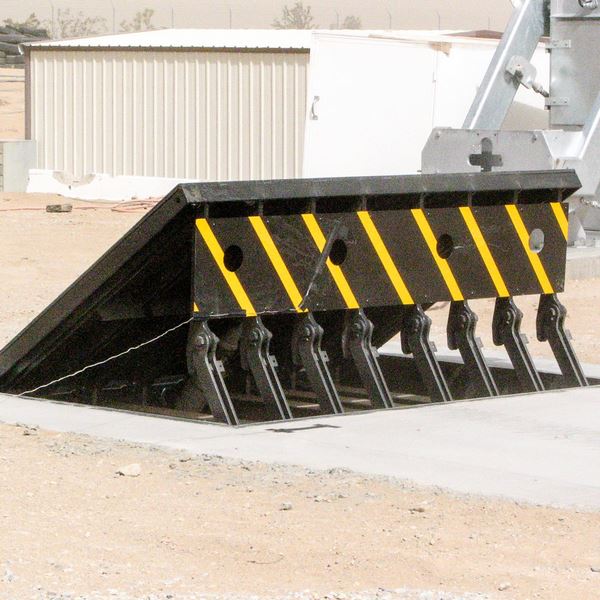
front braces 71. Consequently, the linkage assemblies 72 might pivot and rotate to enable the collapse and expansion of the affiliation settings up 72 throughout retraction and release of the bather 10. The affiliation settings up 72 cause motion of the wedge plate 16 to be restricted. For instance, if a car is taking a trip towards the released wedge plate 16(e. As an example, in one circumstance, the safety and security legs 86 may be expanded duringmaintenance of the obstacle 10. When the safety and security legs 86 are deployed, the security legs 86 support the weight of the wedge plate special info 16 versus the surface area 12. Consequently, the lifting mechanism 50 might be shut down, serviced, eliminated, replaced, etc. FIG. 5 is partial viewpoint view of a personification of the surface-mounted wedge-style obstacle 10, showing the webcam 80 and the cam surface areas 82 of the lifting mechanism 50. Especially, two cam surface areas 82, which are referred to as lower cam surface areas 83, are placed below the web cam 80. The reduced webcam surface areas 83 might be repaired to the surface area 12 (e. For instance, the lower web cam surface areas 83 and the mounting plate 85 might develop a solitary item that is protected to the anchor 30 by screws or various other mechanical bolts. Furthermore, two web cam surfaces 82, which are described as upper web cam surfaces 87, are placed over the webcam 80 and coupled to (e. In various other embodiments, interfering layers or plates may be placed between the surface area 12 and the reduced webcam surface areas 83 and/or the wedge plate 16 and the upper camera surfaces 87 As pointed out over, the see this site webcam
80 converts along the webcam surface areas 82 when the wedge plate 16 is raised from the pulled back placement to the deployed setting. In addition, as discussed over, the spring assembly 54 (see FIG. 3 )might provide a pressure acting on the webcam 80 in the instructions 102 via spring pole 58, which might decrease the pressure the electromechanical actuator 84 is called for to relate to the webcam 80 in order to activate and raise the wedge plate 16. 1 )to the deployed position(see FIG. 4). As shown, the camera 80 consists of track wheels 104(e. g., rollers), which contact and translate along the camera surface areas 82 throughout procedure.